The Beginning
The whole thing started when my 6 year old induction cooker suddenly broke. While I was boiling rice a fuse blew. Resetting the fuse did not help. Since I had little to lose I unscrewed it and hoped to see some obviously broken components.
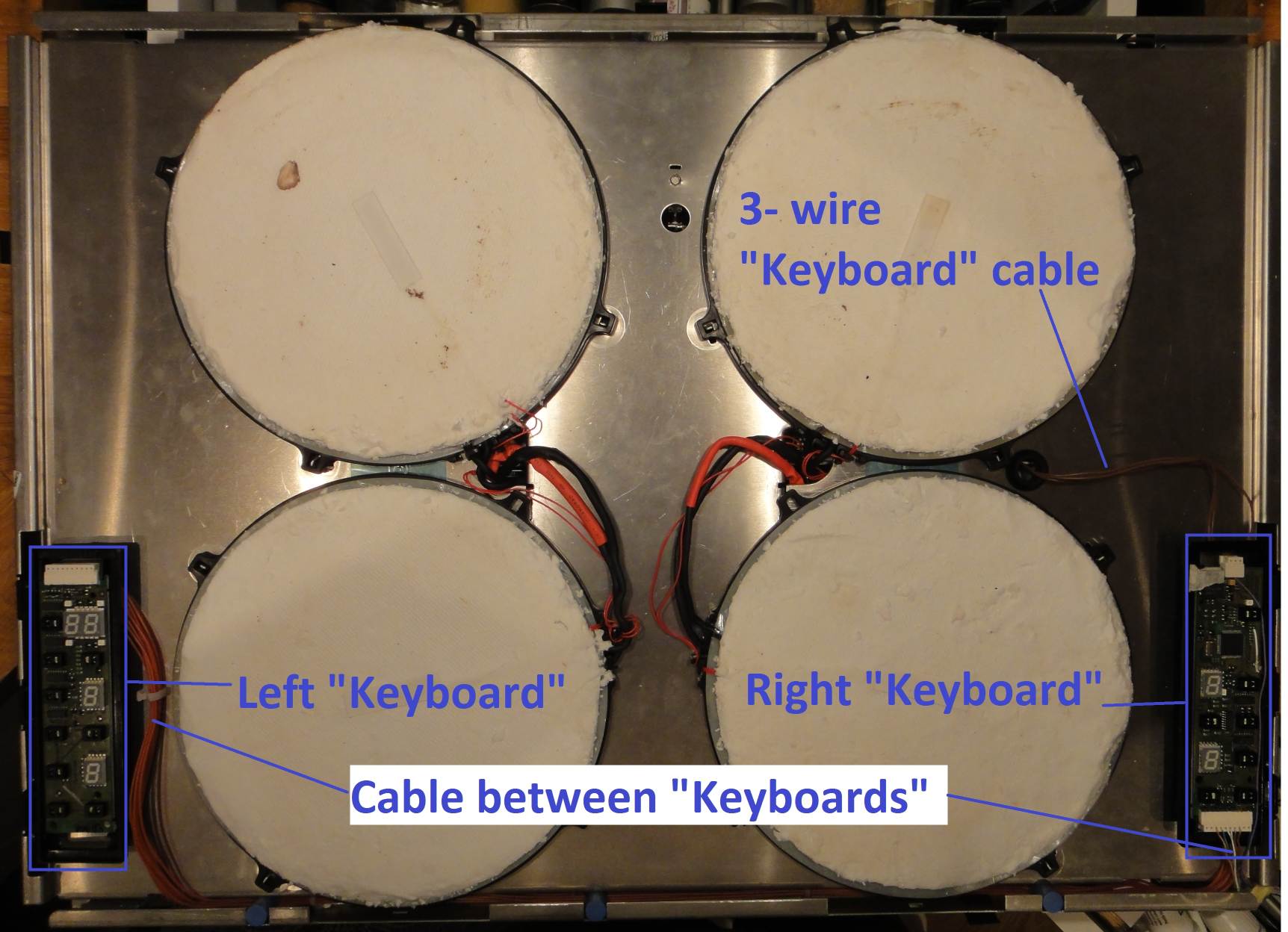
Inside of my induction hob after removing top glass.
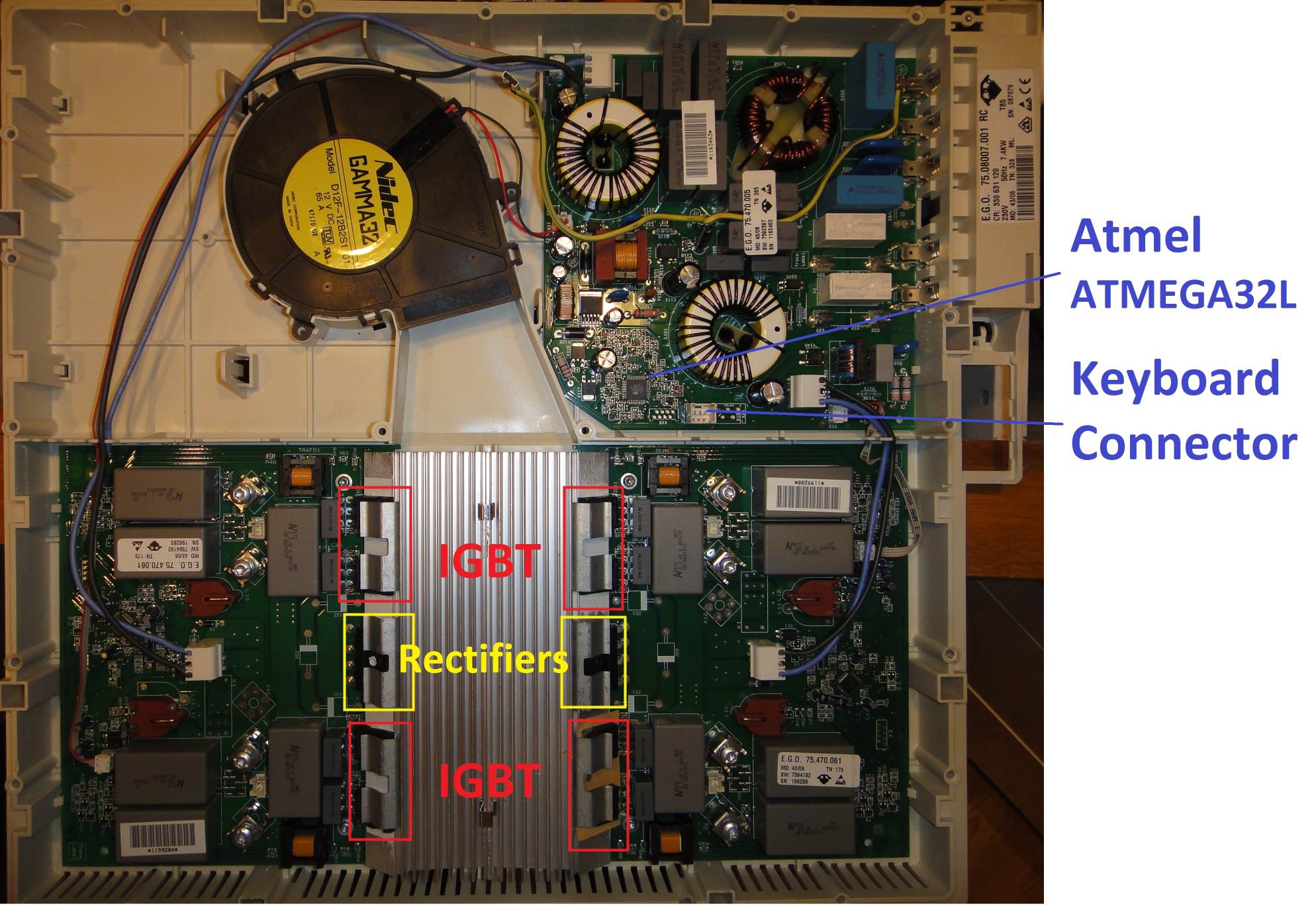
Unfortunately I couldn’t find any so I turned to Internet. After some searching I found a Swedish forum that described the same problem I had. The problem was that two IGBT:s and a rectifier had broke, this was easy to detect by measuring the resistance (there were none). After ordering spare parts (~$30) and some soldering my cooker was up and running again!
The Electronics Inside
However I couldn't help to look a bit at the circuit boards, among some interesting things I found an Atmel ATMEGA32L which I am somewhat familiar with. I also saw that there was only three wires between the “keyboard” and the main power board. The keyboard had a NEC D78F0034AGK which I was not familiar with, but I managed to find the data sheet.

After tracing the wires a bit they seemed to go to the UART pins of the MCU through some transistors.

So I figured it couldn’t be too hard to intercept the data and figure out the protocol that was being used. If I did that I could connect my induction hob to my Android phone and control it from that. You might wonder why you want to control your induction hob from your phone. Everyone I have talked to about this project has asked that question. I guess that that is an indication that I know to few true hackers. I would like to turn the question around: Why are there no induction hobs on the market that you can control from your phone. They can easily cost more than $1000. If you added a <$5 Bluetooth chip to it you could download recipes with correct temperature curves and timing. Just take the Range kickstarter project and you can see that there are more people that would probably want something like this. I needed a way to automate the boiling of the milk for my morning porridge (mannagrynsgröt). If you have ever boiled milk you know how easy it is to burn and boil over the milk.
Let the Reverse Engineering Begin
I ordered a Bus Pirate and while waiting for it to arrive I looked closer to the circuit boards (yes, I have unscrewed my cooker > 20 times by now) and soldered some wires. Once it showed up I connected it and tried to figure out the communication parameters. This took me some time since I was not familiar with the bus pirate. I also had an old firmware that did not include the “Auto Baud Detection” macro. After trying to use the logic analyzer function to measure the bit length without any luck (it just gave me different bit length depending on the sample rate) I went on with trial and error. Some tests later I found out that the correct parameters was 9600bps, even parity and 1 stop bit. The “even parity” was the tricky thing here.
By pressing keys on the cooker and looking at the bytes passing by I could start to see a pattern. Along the way I implemented a parser in Java on my PC. This made it easier to see what bit and bytes I hadn’t understood yet. The protocol sends packets which are acknowledged by the other side (not all of them). Every packet except the “ack” packets have a checksum. Both sides can initiate communication, so there is a risk of collisions, but the probability is quite low, and they can be detected by the missing “ack” packet and/or bad checksum.
Before figuring out this protocol I did not know how much logic that went into the keyboard and how much was in the power card. Was perhaps the keyboard just a dummy keyboard sending the key presses further on to the power card, or was it perhaps smarter. It turned out that it was the later case which was a bit of a problem. If I send a “full power on zone 1” from the PC the display on the keyboard wouldn’t update and after a few seconds the keyboard kept on repeating all power levels to the power card. This meant that I needed a way to simulate key presses to the keyboard.
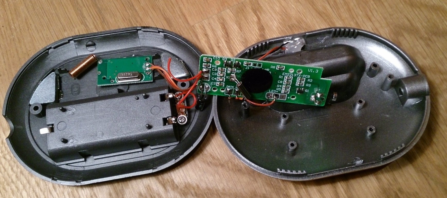
The “Keyboards”
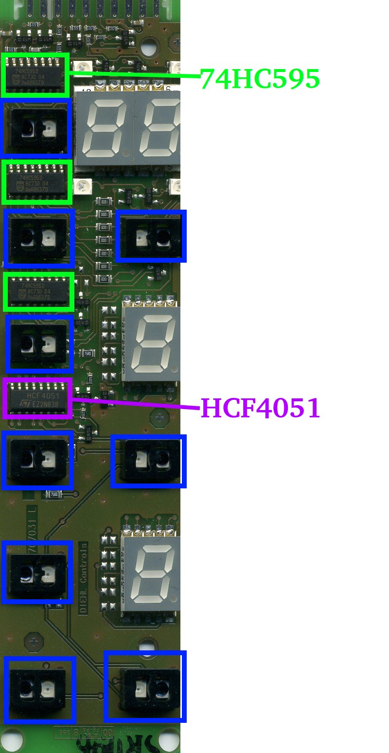
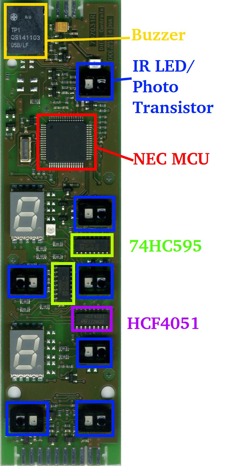
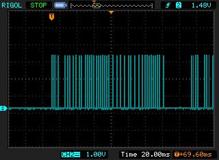
I started to examine the left and right keyboard which consists of two PCB’s. One with a microcontroller and one with some shift registers and an analog multiplexer. The shift registers were used to update the 7-segment numbers and one of them to select the analog input for the multiplexer. The touch input of the keyboard is implemented with an IR diode and phototransistor. When you put your finger close it will reflect the IR light. Somewhere here I realized that I needed an oscilloscope to be able to reverse engineer this part. I decided to go for a Rigol DS5210E.

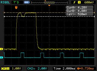
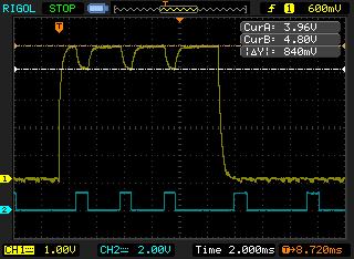
With the help of my new oscilloscope I was able to see that the touch keys are scanned one by one in a sequence by using the 74HC595 shift registers and the HCF4051 analog multiplexers. Every phototransistor is scanned for about 5ms and the IR LED is turned on for about 1ms of this time. This makes it possible to detect and compensate for ambient light and reflections from the induction hob itself. If a reflection is detected it will prolong the scan period to approximately 11ms and turn on the IR LED two more times. All phototransistors, except “main power” one, are scanned using the same analog input.
I could now fake key presses by adding an extra transistor over the phototransistor and send a pulse at the same time as the IR LED is turned on. In order to avoid soldering one transistor for each touch button I connected the transistor to the analog multiplexed line and added a shift register so that I could detect which button that were being scanned. All signals were available on the cable between the two keyboards.
I decided to use a IOIO-OTG as my hardware platform. It can easily be connected with Bluetooth or cable to an Android phone or a PC and the firmware is open source and easy to modify. The IOIO can be fully controlled from the PC/Android, but the speed was too high to correctly read the shift register and set the output so I modified the firmware and added commands to do this. I also managed to measure the scan period which means that key presses being done on the induction hob itself are being detected. This was needed so that a control being made on the Android application can be aborted if someone presses a key on the induction hob.
Adding temperature reading support
The missing part for my project was now a temperature sensor. It would of course be possible to calculate the temperature if the initial temperature, the volume and effect was known, but it is easier and safer to measure it. A 433MHz wireless barbecue thermometer and a 433MHz radio module was purchased. The inside of the barbecue thermometer was easy to understand where the radio module was separated and connected with 3 cables, Vcc, GND and data.
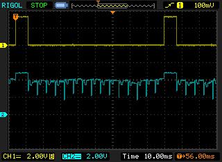
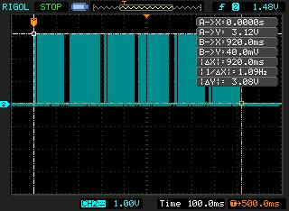
I couldn’t find anyone information about the protocol, but by looking at the oscilloscope it became clear that a 1-bit was sent with a pulse width of ~4.6ms and a 0-bit with a pulse width of ~2.4ms. The whole packet consists of a special start signature of 4 short pulses (=3 0-bits) then a 8.6ms pause followed by 36 bits. Each temperature reading was sent 6 times. The signal on the receiving radio module looked the same but with some additional noise which could be filtered out by measuring the timing.
Once again I modified the IOIO firmware and added support for reading temperature sensor data from the radio module. Then it was easy to write down the data being read and compare it to the known value. There were two tricky things about this, the temperature was sent in Fahrenheit with an offset of 90 degrees (I am a Celsius guy) and the data were swapped nibble-wise. I.e. it looks like this:
   %00111100 00000000 01110011 11011011 0001
    tttttttt tttt              aaaaaaaa
    32107654 BA98
“t” above is the temperature data, and “a” is probably an address that seems to change every power cycle making it possible to use several thermometers at the same time. The unmarked bits are probably checksum, but I haven’t bothered to figure them out yet.
Putting the Whole Thing Together
So now I had everything I needed in order to implement the whole thing: I could inject key presses. I could detect the current power level, I could detect if someone were pressing a key on the induction hob and I could measure the temperature of the milk.

Android Application
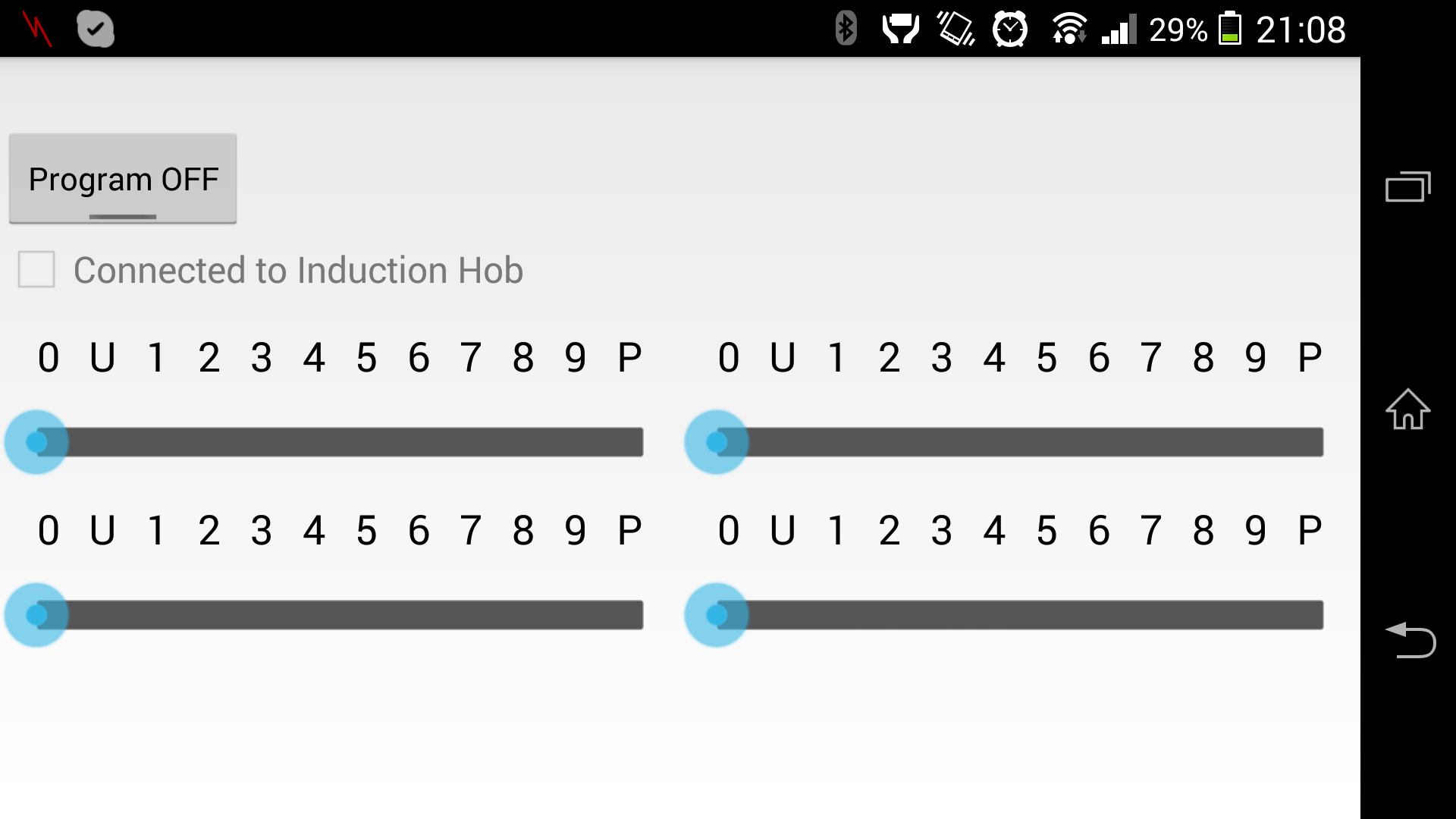
I wrapped all code together and implemented a very basic temperature controller. The last problem was writing the user interface. I don’t like writing user interfaces and they usually ends of looking quite ugly. This time was no exception, but my app gets the job done. Finally I can now boil the milk for my breakfast “mannagrynsgröt” using my Android phone.
Summary
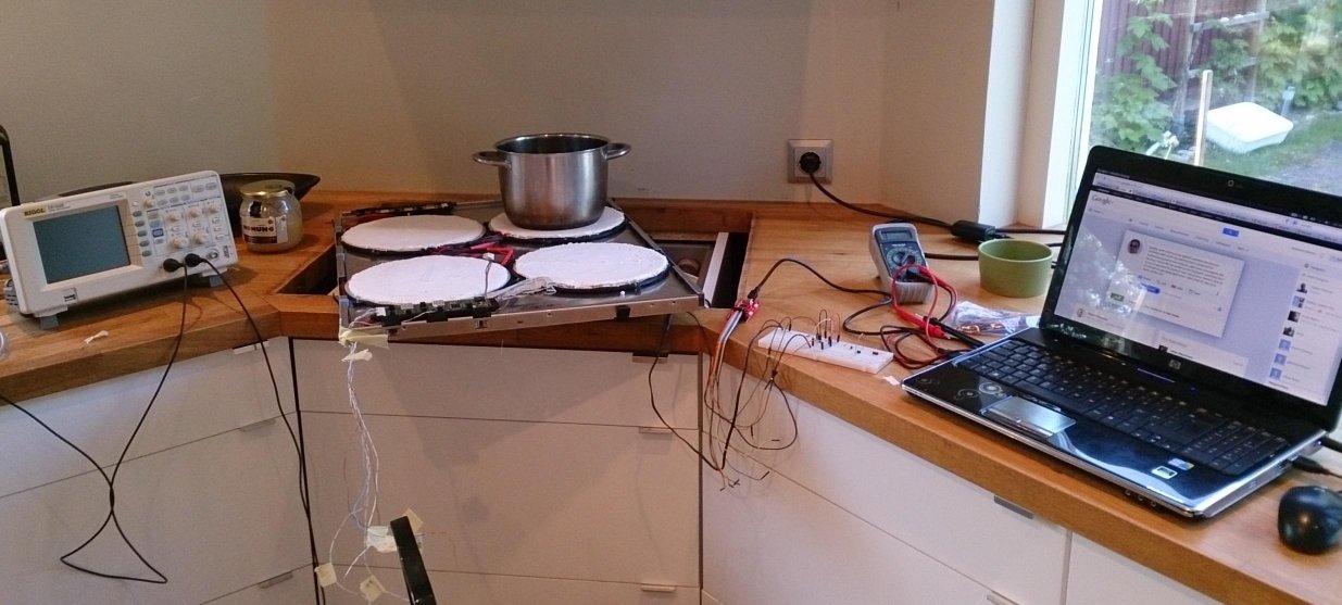
There are lot more to it than mentioned in this text. E.g. A couple of times I have thought that I fried my induction hob: Once I dropped some solder on the PCB without noticing it until I discovered that one zone did not work anymore. Another time I mixed up data and GND pins which caused the induction hob to stop working until next morning (I am still not sure what made it come alive again). This project (including writing this paper) took me more than a year, it is hard to find time when you have 3 kids (the 3rd came during the project) and are working full time (in the beginning I was actually on parental leave, but that does not mean that you have a lot more time to spare). Sometimes it was also not so popular to find the kitchen like the image below when it was time to cook dinner.
The Future
As most projects like these they tend to never be completed. Below are some things that I might do in the future.
- Figure out the checksum part of the temperature sensor.
- Write a better (PID?) temperature controller.
- Better looking UI with learn functionality, different programs, temperature curves etc.
- Create a proper PCB.
Source Code
All source code is available from:https://github.com/johannesc/induction-hob
https://github.com/johannesc/ioio